This lesson challenges students to incorporate both push and variable switches to control the micro:bit’s LED matrix. Students will have to convert the analog values from a potentiometer into an acceptable value that controls the LED matrix.
Aims
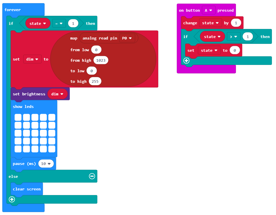
Create two variables that work in conjunction with each other.
Use an analog reading to control the brightness of the micro:bit LED matrix.
Download the Code
MakeCode Editor
Click the button below to download the MakeCode editor code for this lesson. The hex file is contained in a zip folder.
Kindly refer to our download the code page for instructions on how to upload your code onto the micro:bit. Please use instructions set A.
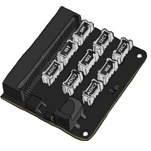
Connect the micro:bit to the Innovation board via the edge connector.
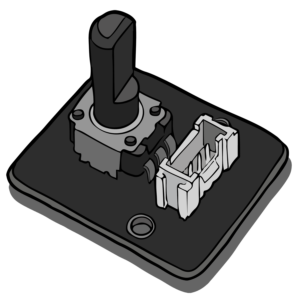
Use the connector cables to connect the potentiometer to the ADC1 connector on the Innovation board.
Connect the micro:bit to a computer via the microUSB cable.
Go to the MakeCode website on your computer and open a new project.
Time to Code
What Will Happen
When button A is pressed the LED matrix will be activated. The potentiometer can be used to vary the brightness level of the LEDs. Turn the potentiometer clockwise to brighten the LEDs and anti-clockwise to dim the LEDs. To turn off the LED matrix press button A.
Taking it Further
Incorporate more devices into the system. Use an LED board instead of the micro:bit.
Keep in touch
We would love to keep you up to date with all of our latest news, offers and new products.
If you would like to subscribe to our mailing list please click the button below.